Tube Tags for Visual Control
Using visual management to reduce processing risk

Workflow Concepts
Making the next action obvious.
Home > Process Integrity > Visually Guided Workflows
4 July 2026 · 4 min read · RoteaHub Editorial
Manufacturing procedures describe what operators should do.
Manufacturing systems should help operators do it.
Rather than depending on memory, verbal handovers or continual, repeated interaction with the Manufacturing Execution System (MES), the facility itself can reinforce the correct sequence of actions.
Resource allocation boards, pass-throughs, ownership tags, incubator labels, workstation status indicators and physical handling points become part of the manufacturing process rather than simply supporting it.
Properly designed, these visual systems should not create additional administrative work. Their state changes naturally as operators perform the manufacturing process.
Each visual element is used to answer a simple operational question.
With respect to a single batch:
From a facility organsiation persepctive:
None of these tools replaces the MES.
Instead, they reduce cognitive load by making the current state of resources immediately visible while allowing the MES to remain the authoritative record of the process.
The following Day 0 walkthrough illustrates how a manufacturing system can progressively guide operators through the complete workflow.
When patient material enters the manufacturing space, the accession process reconciles the documentation with the physical material. The MES initiates the batch record and becomes the authoritative record for all subsequent manufacturing activities.
In this example, the intial procedures are described as the Day 0 process.
The forst step for the patient material is for the contents of an apheresis product contained in a blood transfer pack to be sampled for QC. With incoming materials from diverse origins, the presentaton of the product may not meet the interface needs of the following process. For example, the tubing hanging from the bag may be too short for connection to the processing kit. An ‘open’ manipulation to obtain the samples and adjust or replace the container provides a robust manufacturing interface, despite the additional cost of performing an open procedure.
Once the input products is ready, the goal is to get it into the process promptly.
It is important the resources are available to proceed:
If any resources are not available, the patient material is placed in a controlled escrow location.
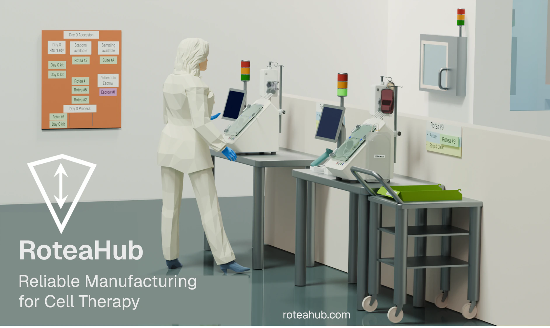
The visual resource board immediately communicates what is available and what is waiting.
The objective is not to begin processing as quickly as possible, but to begin processing only when the manufacturing system is ready.
Once the clean-suite preparation has been completed, the patient material is placed into the outgoing passthrough. The binnacle light ‘attention’ signal triggers an operator to retrieve the product using their ID interacting with the passthrough.
Ownership of the batch now transfers to the receiving operator.
The workstation token identifies the instrument assigned to the batch while a prepared Day 0 kit is retrieved from the supermarket. Removing the kit returns its Kanban token to the “kits required” board, automatically signalling demand for replacement without creating additional administrative work.
The physical movement of tokens becomes the trigger for supply activities.
Responsibility for the batch now transfers to the workstation operator.
Following installation and verification of the processing kit, the automated procedure begins. Early stages of the process may require operator supervision before the instrument completes the programmed sequence independently.
Completion of the Day 0 process creates the intermediate culture product required for incubation.
Although the automated process has finished, the operator’s responsibility continues until every output has reached its next controlled state.
The operator separates the culture vessel from the processing kit and places it into a protective transport tray. The tray ID and culture vessel ID are captured into the MES.
The operator will separate any QC samples generated in the process and verify each has an identity verifiable by the MES before delivering them to the QC passthrough.
Before transporting the product to the incubator, they re-position the station token to the Strip & Clean position.
Another operator, tasked with cleaning actions, will observe that visual state and take over the procedure to remove the kit and clean down the workstation ready for the next batch.
Their reponsibility concludes when they return the workstation token to the accession resources control board.
Completion of the Day 0 process creates the intermediate culture product required for incubation.
The culture vessel, placed into a protective transport tray, is transferred to the incubator by the operator.
Visual cards over the incubator spaces guide the operator to the destination for the product.
The operator records the tray and incubator location where they place it to the MES.
The incubator is more than storage. It becomes the next visual scheduling point. Products are grouped according to the work required on future days so that operators can immediately identify today’s workload and tomorrow’s priorities.
Responsibility transfers once the product has been placed into its incubator location and that location has been recorded in the MES.
The process operator is now released for the next action.
The Day 0 example illustrates several broader design principles that can be applied throughout a manufacturing system.
Every significant manufacturing step includes a clear transfer of responsibility between operators or work areas. Visual cues reinforce these transitions while the MES records them.
Patient material progresses only when the required resources are available. Waiting occurs in controlled escrow locations rather than interrupting other manufacturing activities.
Automation reduces manual effort but does not remove operator responsibility. Visually guided workflows support operator decision-making by presenting available resources, ownership transfers and next actions while automated equipment performs routine processing.
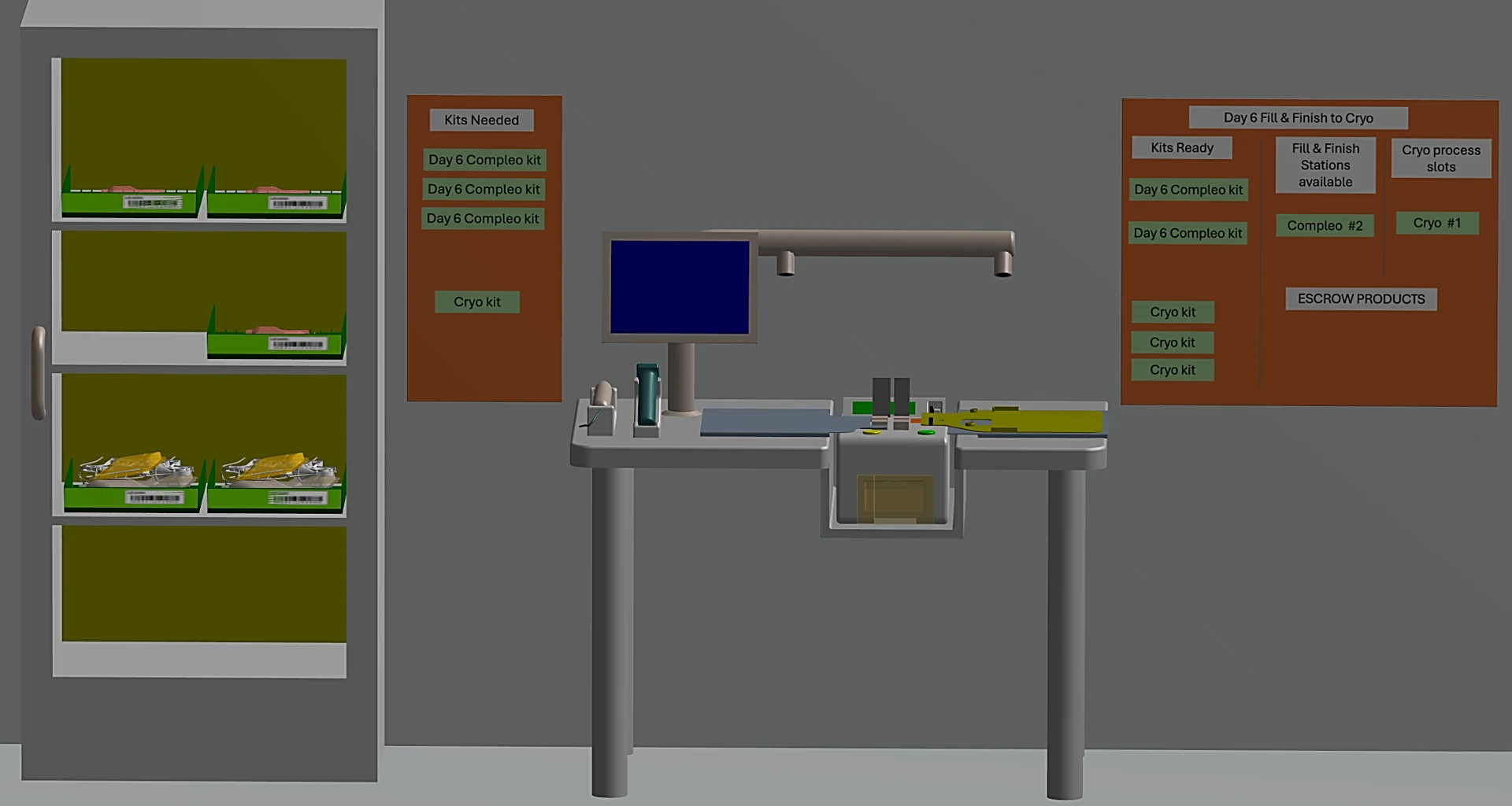
Movement of physical Kanban tokens automatically triggers replacement of kits, reagents and other consumables. Supply activities become driven by actual manufacturing demand rather than forecasts.
Quality Control, clean suites, cryogenic processing and other supporting functions become integrated into the manufacturing workflow through clearly defined interfaces and ownership transfers rather than existing as isolated departments.Quality Control, clean suites, cryogenic processing and other supporting functions become integrated into the manufacturing workflow through clearly defined interfaces and ownership transfers rather than existing as isolated departments.
When disruptions occur, the same visual resource model supports adaptation. Additional resources can simply be added to the available pool, while unavailable resources are removed. The workflow naturally re-forms around the resources that remain available.
Visually guided workflows do not replace procedures or electronic manufacturing systems. They create a resilient manufacturing environment by supporting personnel to respond to changing resource availability, adapt to disruptions and accommodate fluctuating demand.
The objective is not to complete the manufacturing schedule perfectly. The objective is to support the best decision when reality inevitably diverges from the plan.
When facilities are designed so that products, equipment, operators and supporting services communicate naturally, manufacturing becomes easier to understand, easier to supervise and more resilient. Rather than relying solely on procedures to recover from disruption, the manufacturing system itself helps guide the next appropriate action.
Using visual management to reduce processing risk
QC sampling from a functionally-closed system as a robust process.
Shared incubators as a workstation
Process integrity for single use kit assembly
Related reading
Building robust processes
We've sent a 6-digit verification code to your email. Please enter it below.